Background
The front-end amplifier typically dominates the overall noise and power performance of a sensor system. There exists a fundamental tradeoff between noise and power for an amplifier, which is well captured by the noise efficiency factor (NEF). Minimizing this tradeoff (or NEF) is crucial for a wide range of power and energy constrained applications, especially in biomedical implants due to stringent requirements on battery life and heat dissipation. Many excellent research works aim to improve the power efficiency. The central idea is to boost the overall amplifier transconductance (gm) but without increasing the bias current. Classic techniques include: 1) biasing the input pair in subthreshold region to maximize gm/ID and 2) adopting an inverter input stage to reuse the bias current twice.
Technology description
Researchers at The University of Texas at Austin have demonstrated a novel power efficient amplifier. By stacking N inverters and splitting the capacitive feedback into N paths, it achieves 2N-time current reuse for a single-channel input. Unlike other designs, UT’s technology has only N output branches to combine, thus turning exponential dependence into a mild linear dependence. It greatly reduces the total current and achieves the best-reported NEF.
Results
Fig. 1 shows the block diagram of the novel closed-loop inverter stacking amplifier (ISA). The proposed ISA topology works for any integer N. Additionally, Fig. 1 shows an example schematic with N=2. To verify the proposed ISA topology, 2 prototypes were tested in 180nm CMOS: one with 2 stacked inverters and the other with 3 stacked inverters. The 2-stack and 3-stack reported similar gain (25.4 and 25.6 dB, respectively), power consumption (0.23uW and 0.25uW, respectively), and NEF (1.24 and 1.07, respectively). Fig. 2 shows the measured amplifier frequency response. Additional details may be found here.
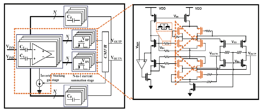 | Figure 1. Conceptual diagram of the proposed inverter-stacking amplifier (left) and a schematic of the 2-inverter stacking amplifier (right).
|
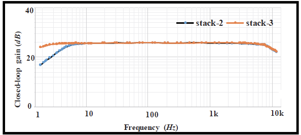 | Figure 2. Measured amplifier frequency response. |